Clock Club
Examples on clocks and time and time setting
Projects in this Repository
Bibliography
Timepieces
Organizations
Software and Hardware Tools
Parts and Suppliers
Notes
Tabletop Clock
aka “What Not To Do” Clock
 Ben Light & Tom Igoe, Jan. 2020
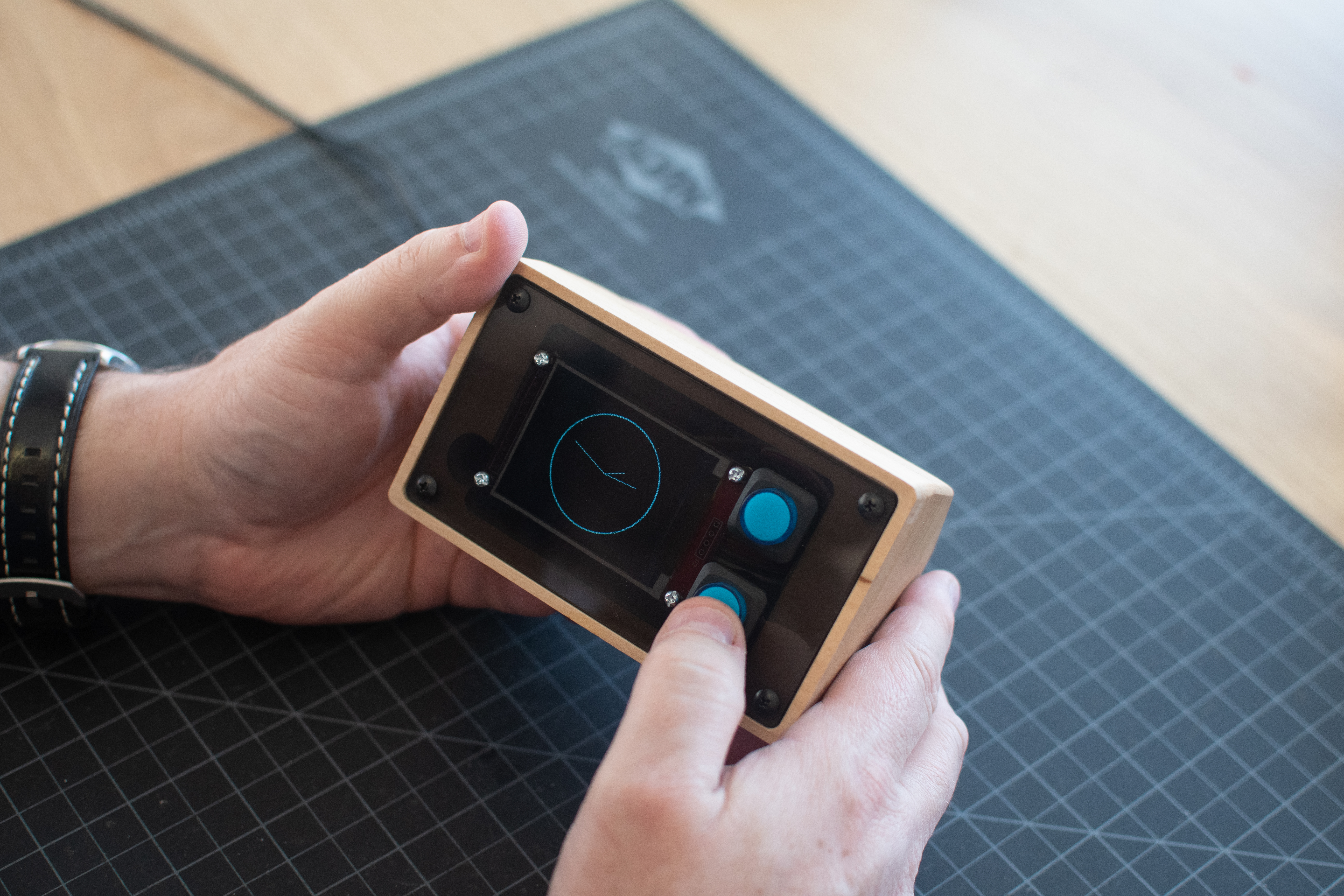
This project is a tabletop clock, designed as a production example for our Tangible Interaction class. We made it to demonstrate how to make a housing for an electronic device with tangible controls from a single block of wood. There are a number of mistakes we made along the way, so we’ve been lovingly referring to it as the “what not to do” clock. Below, we’ve detailed what not to do.
Display and Controls
The device has an LCD screen that displays an analog clock face, two pushbuttons on the front face, and a recessed rotary encoder with pushbutton on the back face. It’s powered by a 5-12V DC power jack in the back.
The rotary encoder is used to set the time. Push the button once to set hours, twice to set minutes, and three times to set seconds. The appropriate clock hand will change colors when it’s the hand to be set. In any of these modes, turn the encoder to move the clock hand. A fourth push puts the clock back into normal operating mode.
The front pushbuttons control the brightness of the screen and the daylight savings mode. One button switches the hour hand back and forth from normal to daylight savings. The other toggles the display between a bright and a dim mode. The buttons light up when pressed, and fade on release.
Housing
The housing was made from a clock of 4”x4” maple that we bought from the art store across the street from our office.
Electronics
The clock runs on an Arduino Nano 33 IoT. We chose this because it is a small form factor, has a built-in realtime clock, and a WiFi/Bluetooth radio that could be used to set the time wirelessly (that option is not currently implemented).
The display is an LCD display from Tinkersphere, the TS-336 TFT LCD display. This was our third choice. We settled on it because it was the best size for our housing, obtainable nearby, reasonably priced, and had an available library with decent documentation for graphics and text.
The first display we looked at before that was the SSD1306 OLED display, an inexpensive display with an I2C interface (and therefore requiring very few pins on the microcontroller). These displays are easy to use, and available from many retailers, but even the larger one was too small for our housing. The other display we considered was the DFR0529, a round TFT LCD display from DFRobot. The display was a good size for our housing, and a round display would have been ideal, but the available library was too slow to update the screen for our tastes, and we didn’t have time to write a new library.
We made one big mistake with the hands in that we used red as the color for the hand being set. It made the hand invisible to red-green colorblind users. So we changed the color to yellow, which is more visible, and hopefully different enough from the blue for most colorblind users to see.
The box cavity started with the circuit board size, which was a huge mistake. Our reasoning was that it was a common size board for our students, easy to learn from. But in making that choice, we compromised the aesthetics of the screen.
The rotary encoder was a Bourns PEC11R-4220K-S0024, bought through Digikey, which we had in stock. The pushbuttons were 16mm illuminated pushbuttons, bought through Adafruit, which we had in stock. We used them because we wanted to show how to use built-in LEDs.
The encoder was a decent choice, but in hindsight, we should have made the cavity of the box deeper so that the encoder could protrude further, and we should have put a knob on it.
The buttons worked well enough, but they aren’t great aesthetically. They overwhelm the screen. Smaller ones like this one from Digi-key would have been better.
Programming
The program is written for the Nano 33 IoT, but it could run on any of the MKR boards, or presumably any Arduino-compatible that uses a SAMD processor with the realtime clock on board.
In programming it, we had to reverse the direction of the encoder from the logical direction, because the user turns the encoder from the back while looking at the front of the clock.